The Workflow Panel
The workflow panel is the central menu for creating your bend solution.
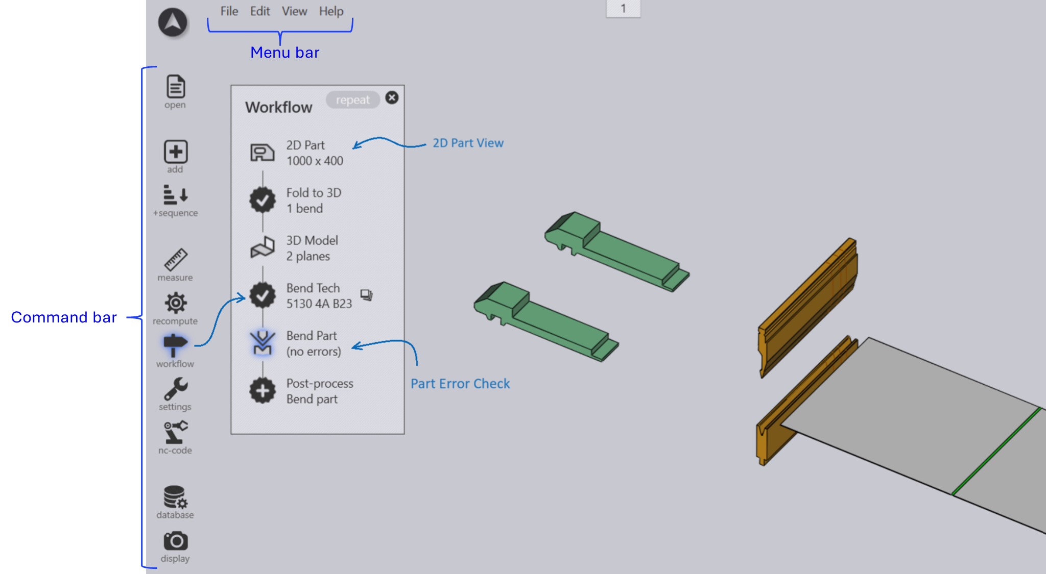
There are different types of nodes in the workflow diagram.
-
Clicking on part view nodes (2D and Laser part, 3D model) switches the part to that 'view' and the set of operations available on the part. For instance, in the Laser Part view, user can edit the laser tooling assigned to the part.
You can switch between these view by clicking on these icons. Hover over the icons to view the shortcuts.
-
The part data is pushed between these nodes by various processes, and they are represented in the workflow panel using the
 icon.
icon.
Processes you have completed have a tick
![]() mark displayed inside. Processes you still have not completed (but which
are available) have a cross displayed
mark displayed inside. Processes you still have not completed (but which
are available) have a cross displayed ![]() inside the icon. You can
click on these process nodes to complete the process.
inside the icon. You can
click on these process nodes to complete the process.
-
Assign Bend Tech (Bend tooling) for the part.
-
Post Process
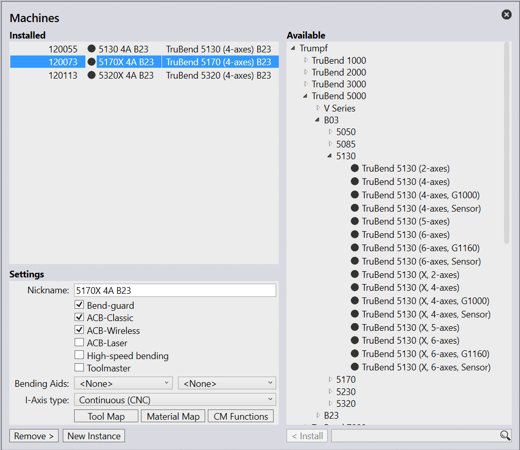
Switch to a different Bend Machine
When you use one of the methods described above, the part normally gets tooled up for the default machine (the same machine that was used the last time). To switch to a different machine:
-
Click on the machine name in the part’s tab on the bottom of the screen.
-
Pick the new machine from the list of bend machines installed (see image below).
-
The part is re-sequenced and tooled for the new machine, and NC code is generated if you have turned that on.